After assembling the switching power supply board and checking the operation,
check the switching waveform of the main part.
Use an oscilloscope to check the voltage and current waveforms,
and check whether the maximum ratings of the main components are exceeded
and whether magnetic saturation has occurred.
Troubleshooting after assembly
Troubleshooting when a switching power supply board does not work properly
immediately after assembly.
The waveforms below show the MOSFET voltage and current.
The waveforms below are the voltage and current of the secondary rectifier diode.
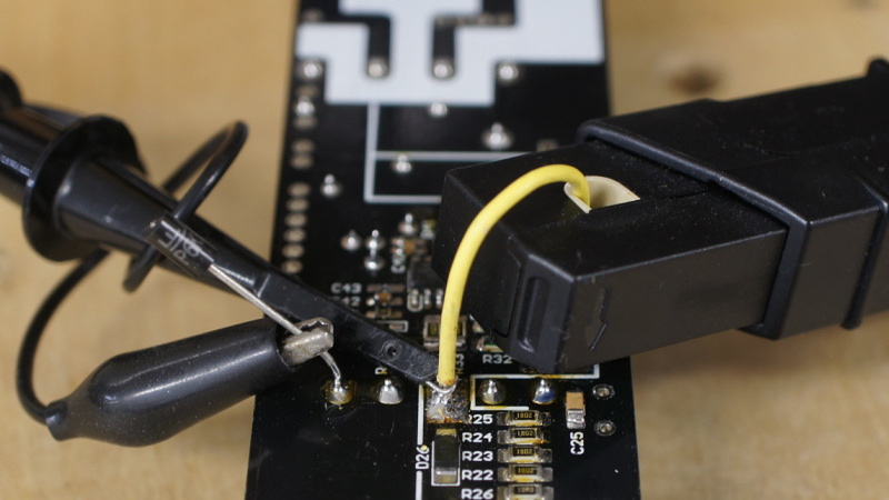
The photo below is a photo taken during the measurement.
Current is measured by cutting the copper foil pattern and using a current
probe.
A current probe with a bandwidth of 50MHz is recommended.
For voltage waveform measurement,
use a probe with a bandwidth of 200MHz or more at 100:1 as shown in the photo.