| Top > Technical-notes > LCRmeter > Measure capacitance |
| Top > Technical-notes > LCRmeter > Measure capacitance |
Understand the operating principle of an LCR meter by measuring and calculating inductance and capacitance.
 |
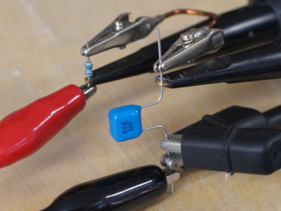
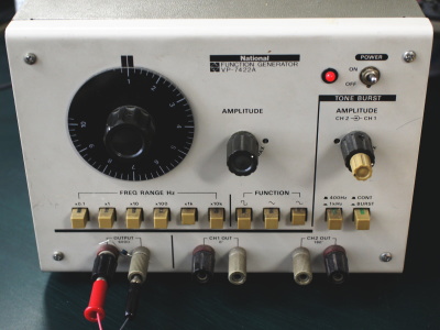
On the left is the measurement circuit. A high precision metal film resistor is recommended for Reference 1kΩ. The bottom left photo is a photo taken during measurement. I used the Function Generator below. |
|
 |
 |
|
The waveform below is the voltage and phase difference of VA1 VA2. |
||
 |
On the left is data obtained from an oscilloscope. | |
Calculate impedance and impedance phase angle based on the data obtained from the oscilloscope. |
||
| Calculate Cs Rs. | ||
 |
 |
|
| Calculate Cp Rp. | ||
 |
 |
|
| What is Cs Cp Rs Rp? How to use LsLpCsCpRsRp Calculation sheet. Click here to download the LsLpCsCpRsRp Calculation sheet. |
||